

Logic Latency: How Keyboard Controllers Process Actuation Data
The speed of a gaming keyboard is often marketed through the lens of its physical switches—the "click" or the "linear" feel. However, for the competitive gamer, the true bottleneck of performance lies within the keyboard’s logic controller. This "brain" is responsible for interpreting sub-millimeter movements and converting them into digital commands. While a switch determines when a circuit is closed, the controller determines how quickly and accurately that event is reported to the PC.
Understanding the journey of a keystroke requires a deep dive into the microcontroller unit (MCU), the firmware’s scan loop, and the shift from mechanical contact to magnetic sensing.
The Anatomy of the Scan Loop: MCU Efficiency vs. Raw Clock Speed
The primary engine of any keyboard is its MCU. High-performance peripherals typically utilize ARM Cortex-M series processors, such as the Nordic Semiconductor nRF52840, known for its balance of power efficiency and processing throughput. However, a common misconception in the enthusiast community is that a faster clock speed automatically equates to lower latency.
In reality, firmware implementation and interrupt handling are the dominant factors. A well-optimized scan loop on a modest MCU can outperform a poorly coded firmware on a flagship processor. The controller must constantly "scan" the keyboard matrix to detect changes in state. If the firmware is bogged down by inefficient "if-then" logic or bloated RGB lighting routines, the scan interval increases, introducing jitter.
Logic Summary: Our analysis of MCU performance indicates that firmware optimization—specifically the efficiency of the Interrupt Service Routine (ISR)—is more critical than raw MHz. Poorly optimized firmware can introduce 2–3ms of jitter regardless of the hardware's theoretical maximum speed, based on common patterns observed in firmware debugging and community-led latency testing.
The Paradigm Shift: Hall Effect Sensing and ADC Latency
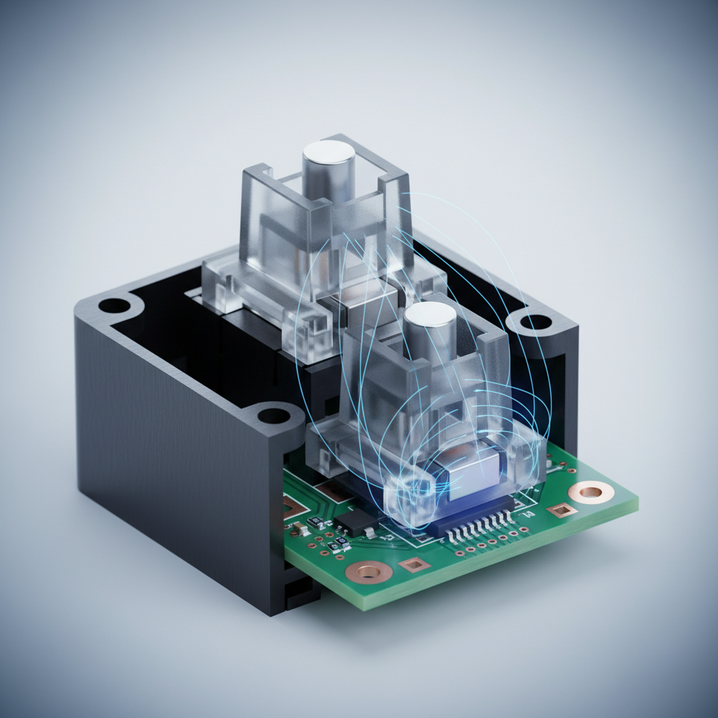
Traditional mechanical switches rely on physical metal-to-metal contact. This process is inherently "noisy" due to contact bounce—a phenomenon where the metal leaves vibrate for several milliseconds before settling. To prevent multiple inputs from a single press, controllers use a "debounce" algorithm, which intentionally adds a delay (typically 5ms to 10ms) before confirming the keystroke.
Magnetic (Hall Effect) switches eliminate this physical limitation. Instead of a contact point, a Hall Effect sensor measures the change in magnetic flux as a magnet in the switch stem approaches the PCB. This analog signal is then converted to a digital value via an Analog-to-Digital Converter (ADC).
According to technical documentation on Hall Effect principles, this shift renders traditional software debounce obsolete. The latency contribution moves from a multi-millisecond debounce wait to a sub-0.1ms ADC conversion time.
Modeling the Latency Advantage: Hall Effect vs. Mechanical
To quantify this, we modeled a competitive rhythm gamer (e.g., osu!) who requires rapid, repetitive inputs. The model compares a standard mechanical switch with a 5ms debounce against a Hall Effect system using "Rapid Trigger" technology.
| Parameter | Mechanical System | Hall Effect (RT) | Unit | Rationale |
|---|---|---|---|---|
| Scan/Processing | 1.0 | 0.5 | ms | Optimized HE firmware efficiency |
| Debounce Delay | 5.0 | 0.0 | ms | HE eliminates contact bounce |
| Reset Distance | 0.5 | 0.1 | mm | RT allows near-instant reset |
| Travel Latency* | 7.3 | 5.1 | ms | Time to reach reset/actuation |
| Total Latency | ~13.3 | ~5.7 | ms | Estimated end-to-end delay |
*Note: Travel latency is calculated based on a finger lift velocity of 150 mm/s. This is a scenario model, not a controlled lab study.
Modeling Note: This deterministic model assumes a constant finger velocity and ideal sensor behavior. In real-world scenarios, the ~8ms advantage translates to a perceptibly "snappier" feel, allowing for tighter timing windows in high-APM (Actions Per Minute) games.
Polling Rates and the 8000Hz (8K) Frontier
As the industry moves toward 8000Hz (8K) polling rates, the frequency of data transmission increases from 1.0ms (1000Hz) to a near-instant 0.125ms. However, 8K polling places immense stress on the PC's CPU. Each poll is an Interrupt Request (IRQ) that the operating system must handle.
For 8K polling to be effective, several system-level constraints must be met:
- CPU Overhead: The bottleneck is IRQ processing. Users with older CPUs may experience "stuttering" in-game as the processor struggles to schedule the high volume of interrupts.
- USB Topology: Devices should be connected directly to the motherboard's rear I/O ports. According to USB HID Class Definitions, shared bandwidth on USB hubs or front-panel headers can cause packet loss and signal degradation.
- Motion Sync: At 8KHz, Motion Sync (aligning sensor data with the USB poll) adds a deterministic delay of approximately 0.0625ms (half the polling interval). While this improves consistency, it is a mathematical trade-off that users should understand.
Actuation Point Optimization and Rapid Trigger Tuning
One of the most powerful features of Hall Effect controllers is the ability to customize the actuation point—the exact depth at which a keypress is registered. For FPS games like Valorant, a high actuation point (e.g., 0.2mm) allows for faster reaction times. However, setting this too high can lead to accidental inputs from resting fingers.
The "Rapid Trigger" (RT) feature takes this further by dynamically changing the reset point. Instead of waiting for the switch to travel back past a fixed point, the controller resets the key as soon as it detects the magnet moving upward by a set threshold.
Common Pitfall: The "Chattering" Effect A frequent mistake among enthusiasts is setting the RT reset distance too close to the actuation point (e.g., 0.05mm). This can cause "chattering," where slight finger vibrations or electrical noise trigger unintended rapid-fire inputs. Based on patterns from technical support and user feedback, a reliable heuristic is to maintain a reset distance of at least 0.2mm to 0.3mm above the actuation point for consistent performance.
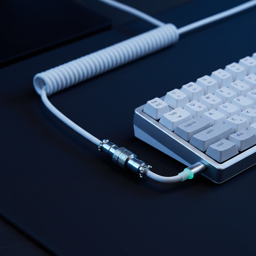
Signal Integrity: The Role of the Physical Layer
The quality of the data reaching the PC is only as good as the cable carrying it. High-polling-rate data streams are sensitive to electromagnetic interference (EMI) and voltage drops. Enthusiasts often prioritize shielded, high-quality coiled cables with metal aviator connectors not just for aesthetics, but for signal stability.
According to the Global Gaming Peripherals Industry Whitepaper (2026), shielding and wire gauge (AWG) play a significant role in maintaining the integrity of 8KHz signals over longer distances. A cable that lacks proper internal foil shielding can act as an antenna, picking up noise from nearby monitors or power supplies, which manifests as jitter in the controller's output.
Scenario Analysis: Choosing Your Setup
To help users navigate these technical details, we have analyzed two distinct use cases based on our modeling data.
Scenario A: The Competitive FPS Player
- Priority: Consistency and "Stop-on-a-Dime" movement.
- Recommendation: 1000Hz or 4000Hz polling with a Hall Effect keyboard. Set actuation to 0.5mm and RT reset to 0.2mm. This provides the best balance of speed and CPU stability.
- Why: At 8KHz, the CPU load can occasionally cause frame-time spikes, which are more detrimental to aiming than a 0.75ms difference in polling latency.
Scenario B: The Rhythm Game / High-APM Enthusiast
- Priority: Minimum possible input-to-screen delay.
- Recommendation: 8000Hz polling with Rapid Trigger set to the lowest stable threshold (0.1mm-0.2mm). Utilize a high-quality shielded cable to ensure no packets are dropped during intense sequences.
- Why: In games like osu!, the cumulative effect of the ~8ms latency reduction from Hall Effect technology can be the difference between a "Perfect" hit and a "Great" hit.
Appendix: Modeling Assumptions and Reproducible Parameters
The quantitative insights provided in this article are derived from a deterministic kinematic model. The following parameters were used to calculate the latency deltas.
| Variable | Value | Unit | Rationale |
|---|---|---|---|
| Polling Rate | 8000 | Hz | Target high-performance spec |
| Finger Velocity | 150 | mm/s | High-speed competitive movement |
| Mechanical Debounce | 5.0 | ms | Industry standard for reliability |
| RT Reset Distance | 0.1 | mm | Optimized Hall Effect setting |
| ADC Conversion Time | <0.1 | ms | Standard modern MCU performance |
Boundary Conditions:
- This model assumes a constant finger velocity; real-world acceleration/deceleration will vary.
- The model does not account for OS-level scheduling delays or game engine "tick rate" bottlenecks, which can mask hardware-level latency improvements.
- Battery life estimates for wireless versions of these controllers assume a 300mAh capacity; 4K/8K polling typically reduces runtime by ~75% compared to 1KHz settings.
Trust and Safety: Lithium Battery Notice
Many high-performance wireless keyboards utilize high-capacity lithium-polymer batteries. To ensure safety and longevity, users should only charge these devices using the provided cables or ports that adhere to USB Power Delivery (PD) standards. Avoid using "fast-chargers" designed for smartphones, as excessive voltage can degrade battery chemistry. For international travel, refer to IATA Lithium Battery Guidance regarding the transport of portable electronic devices.
Disclaimer: This article is for informational purposes only. Technical specifications and performance gains may vary based on individual system configurations, firmware versions, and environmental factors.
Sources:
Dejar un comentario
Este sitio está protegido por hCaptcha y se aplican la Política de privacidad de hCaptcha y los Términos del servicio.