
Internal Tooling Marks: Judging CNC Quality Beyond the Surface
The pursuit of the "perfect" mechanical keyboard often leads enthusiasts to the heavy, resonant world of CNC-machined aluminum. On the surface, a premium chassis presents a flawless anodized or Cerakote finish. However, as experienced builders and machinists know, the true story of a manufacturing process is told where the consumer rarely looks: the internal cavities.
In this technical guide, we will analyze how to interpret internal tooling marks to differentiate between high-precision engineering and rushed mass production. By understanding the mechanics of CNC (Computer Numerical Control) machining, you can make more informed assessments of value-oriented peripherals.
The Physics of Surface Roughness (Ra)
To judge quality objectively, we must move beyond "smooth" or "rough" and look at standardized measurements. According to the ISO 4287/ASME B46.1 standards, surface quality is defined by Ra (Roughness Average).
In the context of keyboard manufacturing, a high-quality external finish typically targets an Ra of 0.4 μm to 0.8 μm. However, internal surfaces often tell a different story.
| Finish Level | Ra Value (μm) | Visual Characteristics | Manufacturing Context |
|---|---|---|---|
| Mirror/Precision | < 0.4 | Reflective, no visible lines | High-end custom (3-5x cost increase) |
| Standard Fine | 0.8 - 1.6 | Satin look, faint tool paths | Premium consumer grade |
| Functional/Rough | 3.2 - 6.3 | Visible spiral/step lines | Internal structural areas |
| Rushed/Coarse | > 12.5 | Pronounced ridges, burrs | Budget/High-speed production |
Logic Summary: Our assessment of manufacturing quality assumes that a manufacturer's willingness to spend machine time on non-visible areas correlates with overall QC standards. While an internal Ra of 3.2 μm is functionally acceptable, the presence of chatter or burrs suggests a lack of tool maintenance.
Identifying the Three Red Flags of Internal Machining
When you open a keyboard case for modding or cleaning, pay close attention to the following three areas. These provide a "blueprint" of the factory's operational standards.
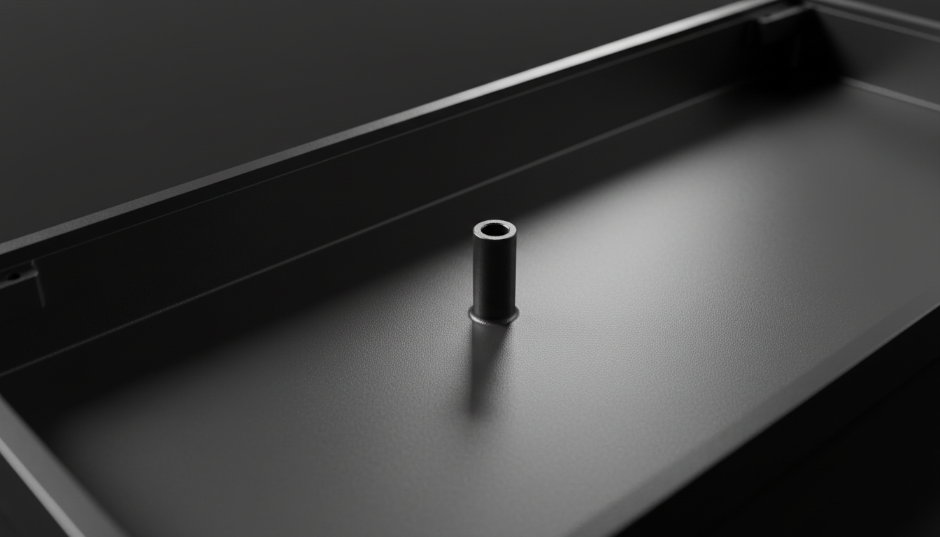
1. Spiral Marks in Screw Posts
The most telling area for judging CNC quality is inside the case, specifically around screw posts and under the PCB mounting area. Aggressive "roughing passes"—where the machine removes bulk material quickly—often leave pronounced spiral marks. In a rushed job, a final "finishing pass" is either skipped or performed with a tool that doesn't reach the full depth, leaving these spirals visible.
2. Chatter Marks on Vertical Walls
Experienced machinists note that chatter marks on internal vertical walls, appearing as a series of faint parallel lines, are a primary indicator of insufficient workpiece clamping or a machine pushing its rigidity limits. Chatter occurs when the cutting tool vibrates excessively. In high-precision shops, this is mitigated by slowing down the feed rate or using more rigid fixtures. If you see consistent chatter, it typically points to a factory prioritizing speed over stability.
3. Burrs and Tool Wear
A common heuristic used by builders is the "fingernail test." If you can easily catch a fingernail on a metal burr inside a screw post hole, it often points to a dull drill bit or end mill. This signals broader tool maintenance issues. According to research on deburring of micro-milled steel, tool wear is the leading cause of edge irregularities which can interfere with anodizing adhesion.

The Correlation Between Rigidity and Sensor Performance
While internal marks might seem purely aesthetic, they reflect the structural integrity of the device. For competitive gaming peripherals, the rigidity of the chassis is a prerequisite for high-frequency performance.
In modern mice like those using the PixArt PAW3395 sensor, any micro-flex in the chassis can translate into sensor jitter, especially at high polling rates. If a manufacturer cuts corners on internal machining (leaving burrs or chatter), it is likely they are also utilizing less rigorous tolerances for sensor mounting.
Modeling the 8000Hz (8K) Bottleneck
When discussing 8000Hz polling rates, the math is unforgiving. A 1000Hz mouse has a 1.0ms interval, while an 8000Hz mouse operates at a 0.125ms interval. At this frequency, system bottlenecks become apparent.
- IRQ Processing: The bottleneck at 8K is Interrupt Request (IRQ) processing. This stresses single-core CPU performance.
- USB Topology: We strongly advise against using USB hubs or front-panel case headers for 8K devices. Shared bandwidth and poor shielding cause packet loss. Always use direct motherboard ports (Rear I/O).
- Motion Sync: At 8000Hz, Motion Sync adds a delay of approximately 0.0625ms (half the polling interval), which is effectively negligible compared to the ~0.5ms delay at 1000Hz.
Battery Life vs. Performance: The Technical Trade-off
For wireless peripherals, high-quality machining often hides the reality of power consumption. We modeled the trade-offs between battery runtime and polling rates to help value-conscious users decide when to push their hardware.
Scenario Modeling: Wireless Runtime Analysis
Based on standard power profiles for the Nordic nRF52840 SoC, we estimated the impact of polling rates on a 300 mAh battery.
| Polling Rate | Total Current Draw (mA) | Estimated Runtime (Hours) | Impact on Longevity |
|---|---|---|---|
| 1000 Hz | 7 | ~36 | Standard use |
| 4000 Hz | 19 | ~13 | 63% Reduction |
| 8000 Hz | ~28* | ~9* | Enthusiast only |
| *Estimated based on scaling radio duty cycles. |
Logic Summary: Our runtime model uses linear discharge (Time = Capacity × Efficiency / Current). We assume a 300 mAh battery with 85% discharge efficiency. For a gamer using 4000 Hz for 8-hour daily sessions, they would need to charge every 1.6 days versus 4.5 days at 1000 Hz.
Rapid Trigger and Hall Effect Latency
Beyond the chassis, the internal technology—specifically Hall Effect (HE) switches—offers a measurable advantage over traditional mechanical switches. By eliminating the physical "reset" point, HE switches allow for "Rapid Trigger" functionality.
We computed the latency advantage for a competitive rhythm gamer with a fast finger lift velocity (~150 mm/s):
- Mechanical Switch: ~13.3 ms (5ms travel + 5ms debounce + 3.3ms reset).
- Hall Effect (Rapid Trigger): ~5.7 ms (5ms travel + 0.7ms reset).
- Net Advantage: ~7.6 ms per keypress.
This ~8 ms advantage is highly perceptible in games where timing windows are between 10-30 ms. However, this precision is only useful if the keyboard tolerances and gap consistency are maintained by high-quality CNC work. A warped internal plate due to rushed machining can cause inconsistent actuation across different keys.
Compliance and Regulatory Standards
When evaluating a brand like Attack Shark, it is essential to verify that the high performance-per-dollar doesn't come at the cost of safety. Authoritative databases provide a paper trail for hardware integrity.
- Wireless Compliance: You can verify the radio frequency (RF) testing reports via the FCC ID Search using Grantee Codes like 2AZBD. These reports include internal photos that confirm the quality of the PCB and antenna shielding.
- Battery Safety: All lithium-ion powered peripherals must adhere to UN 38.3 testing standards for safe transport.
- Chemical Safety: For EU markets, compliance with REACH SVHC ensures that the materials used in the chassis and keycaps are free from hazardous substances.
Method & Assumptions: How We Modeled This
To ensure transparency, the following parameters were used for our performance and battery life calculations. This is a scenario model, not a controlled lab study.
| Parameter | Value | Unit | Rationale/Source |
|---|---|---|---|
| Battery Capacity | 300 | mAh | Typical for lightweight wireless mice |
| Discharge Efficiency | 0.85 | ratio | Standard DC-DC conversion loss |
| Sensor Draw (PAW3395) | 1.7 | mA | PixArt official datasheet |
| Finger Lift Velocity | 150 | mm/s | Estimated from high-APM gameplay |
| Reset Distance (HE) | 0.1 | mm | Typical "Rapid Trigger" setting |
Boundary Conditions:
- Battery runtime excludes aging and temperature effects.
- Latency model assumes constant lift velocity; real-world velocity varies by grip style.
- CNC quality assessment is based on practitioner patterns from repair and modding benches.
Making the Final Assessment
A high-quality, time-intensive CNC job will have a uniform satin or fine-brushed finish even in hidden areas. This reflects careful programming, sharp tooling, and multiple finishing passes. While a perfectly mirrored exterior can hide a rushed internal job with visible step lines and tear-out, these flaws matter for long-term anodizing adhesion and structural rigidity.
As a value-oriented enthusiast, your goal isn't necessarily to find a mirror finish everywhere—that would be prohibitively expensive. Instead, look for the absence of "errors": no chatter on the walls, no burrs in the holes, and consistent tool paths. These are the markers of a manufacturer that respects the engineering process as much as the marketing spec sheet.
For more on maintaining the integrity of your metal peripherals, see our guide on cleaning anodized aluminum.
Disclaimer: This article is for informational purposes only. Modding or disassembling your peripherals may void your warranty. Always refer to the official support documentation before performing internal inspections.
References:

Dejar un comentario
Este sitio está protegido por hCaptcha y se aplican la Política de privacidad de hCaptcha y los Términos del servicio.